ddk-fpga
Table of Contents
Introduction
This repository contains the HDL and constraint files necesseray for building the FPGA bitstream. This repository also contains the testbenches and macro files used for simulation and verification of the behavioral model. The DDK currently utilizes a Microsemi ProASIC3 Nano 125 A3PN125 FPGA.
Hardware Design
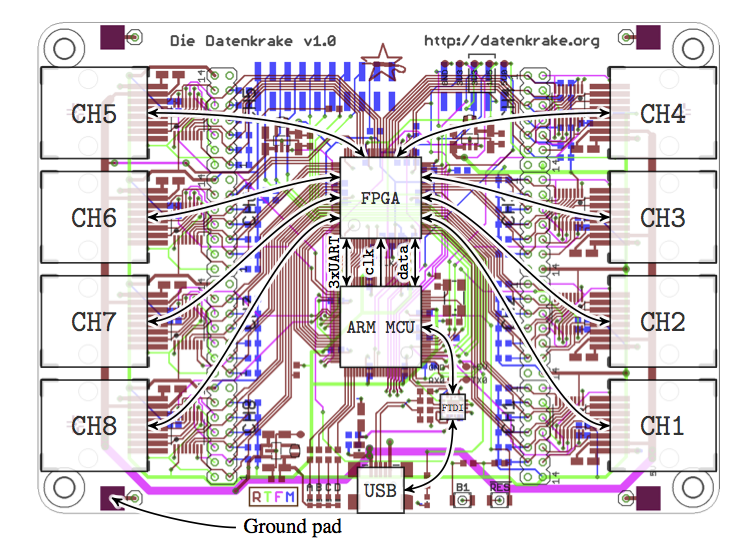
The hardware is designed to provide as much flexibility as possible to custom applications. The ARM and the FPGA share the following connections:
  ARM        Signal       FPGA        Usage
________   __________   _________   __________
 P1[27]     CLKOUT       Pin 11      SysClk

 P1[16]     DATA[0]      Pin 23      DATA[0]
 P1[17]     DATA[1]      Pin 22      DATA[1]
 P1[18]     DATA[2]      Pin 21      DATA[2]
 P1[19]     DATA[3]      Pin 20      DATA[3]
 P1[20]     DATA[4]      Pin 19      DATA[4]
 P1[21]     DATA[5]      Pin 16      DATA[5]
 P1[22]     DATA[6]      Pin 15      DATA[6]
 P1[23]     DATA[7]      Pin 13      DATA[7]

 P2[0]      DATA[8]      Pin  3      DATA[8]
 P2[1]      DATA[9]      Pin  2      DATA[9]
 P2[2]      DATA[10]     Pin 95      DATA[10]
 P2[3]      DATA[11]     Pin 96      DATA[11]
 P2[4]      DATA[12]     Pin 97      DATA[12]
 P2[5]      DATA[13]     Pin 98      DATA[13]
 P2[6]      DATA[14]     Pin 99      DATA[14]
 P2[7]      DATA[15]     Pin 100     DATA[15]

 P0[15]     TX1          Pin 4       TX1 (TestMode)
 P0[16]     RX1          Pin 5       RX1
 P0[10]     TX2          Pin 6       SysRst
 P0[11]     RX2          Pin 7       TestEn
 P0[0]      TX3          Pin 8       DataClk
 P0[1]      RX3          Pin 10      DataWe
The ARM column is the pin name for the LPC ARM microcontroller. Signal is the signal name in the CAD schematic and board files as well as in the top module. Finally, usage is what the pin is used for in the current DDK architecure.
Architecural Design
The top module provides a wrapper around all of the vendor specific I/O and the CAD signal names.
Internally the core achitecture implements the open-source Wishbone interconnect to interface modules.
The parallel data bus DATA as well as the DataClk and DataWe signals are converted to signals conforming to the Wishbone interconnect in the krake_bus module.
To generate the necessary strobe signals for individual modules, addresses defined in the reg_defs are matched in the ddk_core. The addresses also switch a DAT/ACK multiplexer that ensures that there is no bus contention among these bus lines. Currently there is no facility to read data from the FPGA, but this is the architecture that will be used in future designs.
Integrating Custom Modules
Since the FPGA provides a Wishbone interface internally, modules conforming to the Wishbone interconnect can be integrated very easily. The krake_port module is a simple example of a such a module. The krake_port utilizes all 6 available GPIO pins available per channel. This module implements bit banging, as well as the capability to output clocks generated on the DDK.
The DDK architecture utilizes the following signals per channel:
1
2
3
4
5
6
7
8
9
10
11
input wire clk_i, // Wishbone clock
input wire rst_i, // Wishbone reset
output reg ack_o, // Wishbone module ack
input wire [7:0] dat_i, // Wishbone data input
input wire [3:0] adr_i, // Wishbone address input
output reg [7:0] dat_o, // Wishbone data output
input wire stb_i, // Wishbone strobe
input wire we_i, // Wishbone write enable
input wire [5:0] ch_in, // Channel I/O input
output reg [5:0] ch_out, // Channel I/O output
output reg [5:0] ch_oe, // Channel I/O output enable
By replacing instances of the krake_port module in the core no further modifications to the core are necessary.
It is best practice to explicitly set channel I/O pins to disabled, i.e. ch_oe[0] <= 1'b0;.
For modules that don’t directly replace an instance of a channel module, the strobes and multiplexers must be configured accordingly to accomidate the new module.
The channel I/O signals may also need to be omitted if the module does not interface to the outside world, see clk_gen.
Libero SoC Toolchain
For development for the Microsemi FPGAs the Libero SoC Suite and a free Libero Gold License is required. To obtain a lincese you must register with Microsemi. The following outlines the steps necessary for installing the toolchain.
Requesting a license
- Register for an account on the Microsemi Support Portal.
- Request a product license in the Microsemi Support Portal. Login and click “Request free license”.
- Select the “Libero Gold Node Locked for Windows” license option. Note, we recommend using the Windows version of the toolchain.
- Enter a “DiskID” into the form.
The easiest way to get a volume ID is to execute
Vol C:in Command Prompt. - At this point you should have successfully requested a license. The license requests usually take less than an hour.
Installing the software.
- Next, download the latest version of Libero SoC here. Again, we recommend using the Windows version of the toolchain. We recommend installing the (large) “Self-Contained EXE” versus the “Web Install EXE”.
- During installation you may be prompted to install install either “Libero SoC” or “Libero SoC SA (Standalone)”. Select the “Libero SoC” version.
- When prompted, make sure you select and install atleast the ProASIC 3 Nano FPGA libraries. Note: you can also do this after the installation by starting “Uninstall or Modify Libero SoC” from the start menu and modifying the installation.
- After installation and once you have recieved your license, you can install it using the Actel License utility. This utility sets an enviornment variable that points to the License file, hence you may need to log out or restart the machine.
- To verify that the license is working, try starting “Synopsys Synplify”. If you do not see license errors, than the license has been installed correctly.
Linux installation.
We do not support the linux toolchain, however, people have reported this to be working. If you wish to use the Microsemi toolchain under Linux, you can try Matt Gardner’s linux instructions here.